

How To Find Cutoff Frequency Of Low Pass Filter
Omni's cutoff frequency calculator allows you to calculate the cutoff frequency of various filter's circuits. If you don't know what cutoff frequency is or how to calculate it, worry not! Read this article to understand the definition and formula of the cutoff frequency. You will also find an example of how to determine the cutoff frequency of a low pass RC filter circuit.
What is cutoff frequency? — cutoff frequency definition
The cutoff frequency or corner frequency of an electronic circuit is the frequency at which the output signal of the system starts reducing. More precisely, at the cutoff frequency, the ratio (Output power)/(Input power) attenuates by a factor of 1/2 or the voltage gain (Output voltage)/(Input voltage) attenuates by a factor of 1/√2.
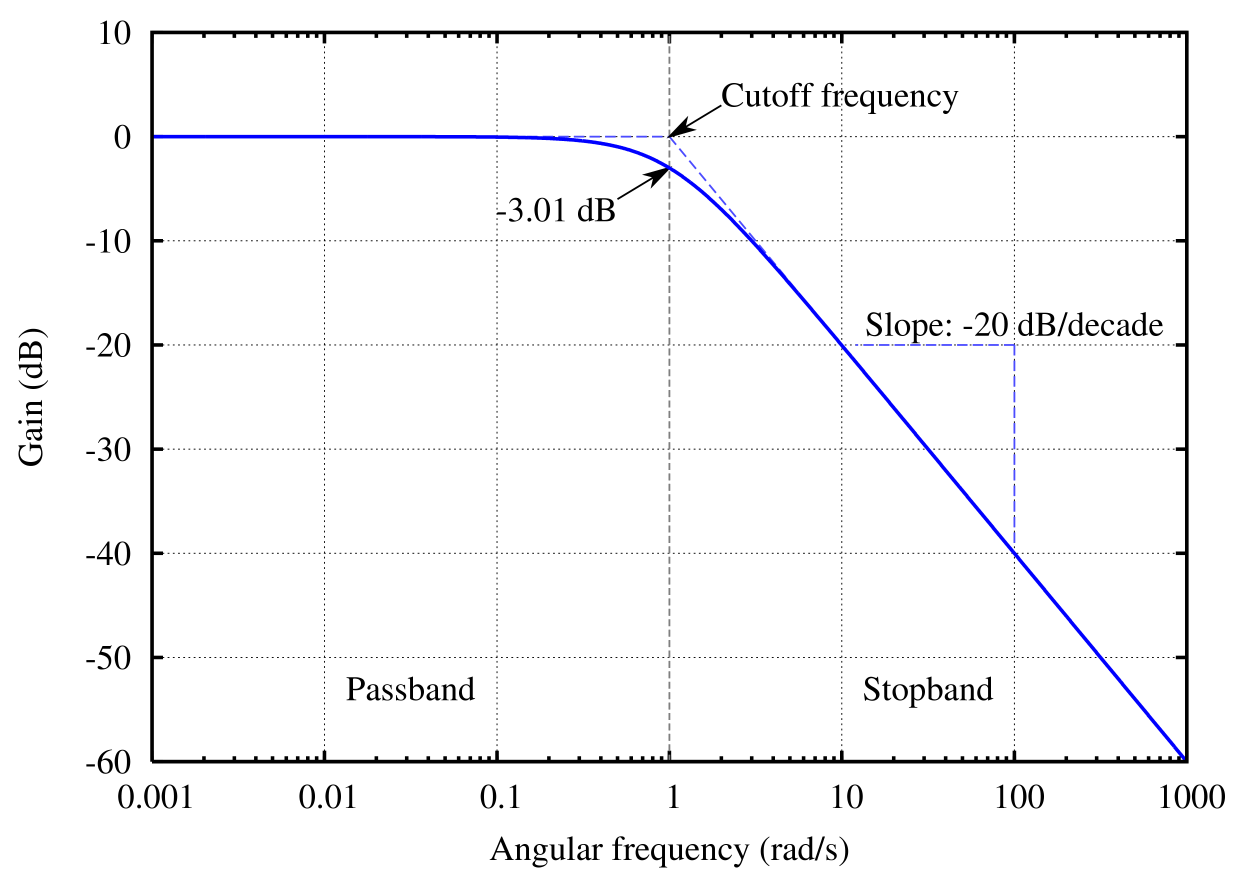
To understand this let us consider figure 1 which shows the voltage gain of a circuit over a wide range of frequency. We can express the gain of the circuit in decibel as:
Gain (dB) = 20 log10 (Output voltage / Input voltage).
Initially, when the Output voltage = Input voltage:
Gain (dB) = 20 log10(1).Since log10(1) = 0 , we can write:
Gain (dB) = 0 At the cutoff frequency:
(Output voltage) / (Input voltage) = 1 / √2
Gain (dB) = 20 log10(0.707) = -3 dB
As you can see, at the cutoff frequency, the gain of the circuit is -3 dB. Hence, the cutoff frequency is also sometimes known as -3 dB frequency.
Cutoff frequencies are important characteristics of any filter circuit. Before going any further, let us first try to understand what a filter circuit is.
What is a filter circuit?
Filters are electronic circuits that allow certain frequencies to pass through them and block other frequencies. The two most commonly used filter circuits are:
- The low-pass filter; and
- The high-pass filter.
As the name suggests itself, a low pass filter allows low-frequency signals (from 0 Hz to a cutoff frequency) to pass through and attenuates high-frequency signals. A high pass filter allows high-frequency signals (above a cutoff frequency) and impedes low-frequency signals.
It is worth noting that the output signal is not completely blocked at the cutoff frequency, but gets more and more attenuated as we move to higher frequency regions (see figure 1).
In the following sections, we will discuss the corner frequency formula for these two types of filter circuits.
Formula for cutoff frequency of RC filter circuit
An RC filter circuit consists of a resistor (R) and a capacitor (C). Figure 2 shows the circuit diagram of a simple low pass RC filter. We know that the capacitive reactance (i.e., the resistance offered by a capacitor to the current flowing through it) is inversely proportional to frequency. Therefore, it will offer very high impedance at low frequencies, and we can consider the capacitor circuit as open. This means that Vout is equal to Vin at low frequencies. At higher frequencies, the capacitive reactance in very low and this results in a lower output voltage as compared to the input voltage.
The formula for calculating cutoff frequency for an RC filter circuit is:
fc = 1 / (2 * π * R * C) 
Formula for cutoff frequency of RL filter circuit
Figure 3 shows a simple high pass RL filter circuit consisting of a resistor (R) and inductor (L). This circuit only allows high-frequency signals to pass through. The inductive reactance (i.e., the resistance offered by an inductor to the current flowing through it) is directly proportional to the frequency of the signal. The inductor circuit offers high impedance to high-frequency signals, and hence can be considered as an open circuit. This means that Vout is equal to Vin at high frequencies. For low-frequency signals, it offers little to no resistance, and hence the voltage drop across it is negligible, resulting in a low output voltage.
The formula for calculating cutoff frequency for a RL filter circuit is:
fc = R / (2 * π * L) 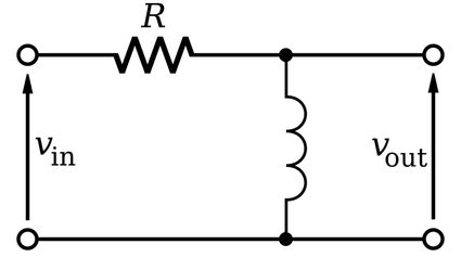
The corner frequency formula for high pass filter circuits and low pass filter circuits is the same.
How to calculate cutoff frequency?
Let us calculate the cutoff frequency of a low pass RC filter circuit consisting of a 10 k Ω resistor connected in series with a 25 nF capacitor.
-
We can express the resistor and capacitor values as:
R = 10 * 103 ΩandC = 25 * 10-9 F. -
We can write the cutoff frequency equation for RC filter circuit as:
fc = 1 / (2 * π * R * C ). -
Substituting the given values of resistor and capacitor in the above equation, we get:
fc = 1 / (2 * π * 10 * 103 Ω * 25 * 10-9 F)fc = 636.6 Hz.
How to use the cutoff frequency calculator?
Now let us work out the same problem using our cutoff frequency calculator:
-
Using the drop-down menu, select the filter circuit type as RC.
-
Enter the value of resistance as
10 kΩ. -
Type the value of capacitance as
25 nF. -
The calculator will display the cutoff frequency (
fc), i.e.,636.6 Hz. -
As the cutoff frequency formula of a high pass RC filter is the same as that of a low pass RC filter, you can use this calculator for both.
FAQ
What is cutoff frequency in low pass filter?
The cutoff frequency of a filter is the frequency at which the magnitude of the output voltage signal drops by a factor of 70%. A low pass filter allows frequencies between 0 Hz and the cutoff frequency to pass through and attenuates higher frequencies.
Why the cutoff frequency is taken at -3dB?
The decibel is a logarithmic scale expressed as 20 log(Output power/Input power). A -3 dB gain corresponds to an (Output power/Input power) ratio of 0.5, i.e., the output power of the circuit reduces by a factor of half. This serves as a standard reference for defining the boundary in the frequency response of a system.
How do I determine cutoff frequency of low pass filter?
To determine the cutoff frequency of a low pass RC filter, follow these instructions:
- Multiply the value of resistance (
R), capacitance (C), and2π. - Divide the value obtained in the previous step by
1. - Congrats! You have calculated the cutoff frequency of a low-pass RC filter.
How to find the cutoff frequency of high pass RL filter?
To find the cutoff frequency for a high pass RL filter, proceed as follows:
- Multiply the inductance value (
L) with2π. - Divide the resistance (
R) by the value from step 1. - You have determined the cutoff frequency of the high pass RL filter.
Purnima Singh , PhD
How To Find Cutoff Frequency Of Low Pass Filter
Source: https://www.omnicalculator.com/physics/cutoff-frequency
Posted by: lainezdrinnera76.blogspot.com
0 Response to "How To Find Cutoff Frequency Of Low Pass Filter"
Post a Comment